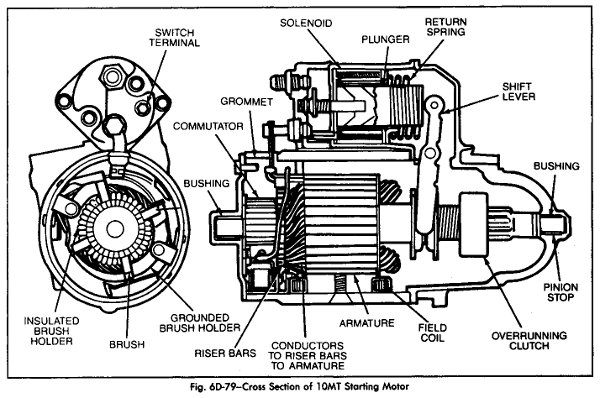
This guide contains information about the Delco-Remy 10MT starter that was commonly used on Chevrolet gas engines from 1956 up into the 90's. The 10MT starter was also used on a variety of other GM and non-GM vehicles and equipment.
There are two basic versions of the motor itself (low and high torque) as well as numerous different drive-end nose pices to fit various applications. This guide shows the 5 most common nose pieces used on Chevrolet engines from the mid 50's into the 70's.
Low and High Torque Versions
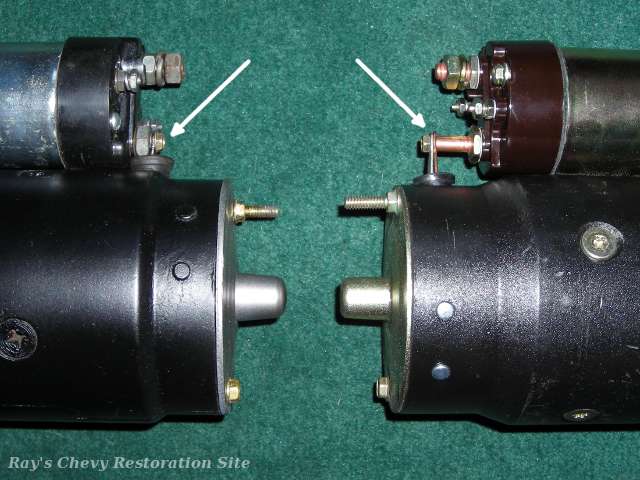
The regular "low torque" version of the 10MT motor has the solenoid screwed directly to the metal strap leading inside the starter motor. An example of this type of starter is shown on the left in the above photo.
The "high torque" version of the 10MT motor has a spacer bushing and a long screw to connecting the solenoid to the metal strap leading inside the motor. An example of this type of starter is shown on the right in the above photo.
Note: Some rebuilt starters may have the shorter "low torque" field coils inside a "high torque" field frame (housing). Removing the end cover to examine the field coils is the only way to be sure a starter is truly a "high torque" version.
Solenoid Information
The solenoids used with these starters serve a dual purpose. They (1) have a set of high current contacts that feed battery power to the motor. And they (2) pull on a plunger that is in turn connected to a shift fork that moves the pinion gear outward to engage it with the ring gear on the flywheel or flexplate.
Note: For the most part, the solenoids are interchangeable between the various starters shown in this guide. However, there are some variations in the size of the metal plunger that goes inside the solenoid. So when replacing a solenoid or piecing together a starter from parts, care must be taken to match the solenoid to the plunger.
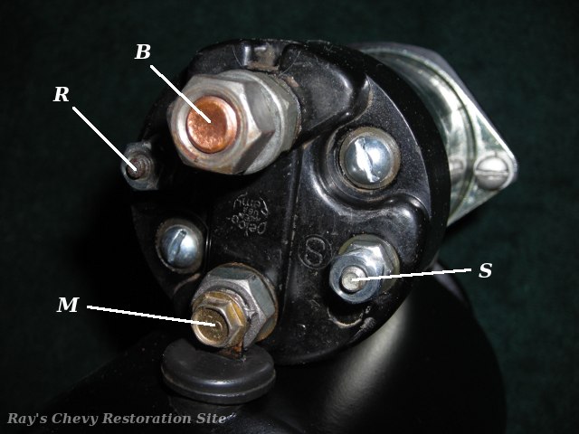
Solenoid Connections:
| Terminal | Thread Size | Connections / Usage |
|---|---|---|
| B | ⅜" - 16 | Positive battery cable. Some vehicles also have an additional wire or two (usually red and protected with a fusible link) connected to this stud to feed power to various other circuits. Some factory ammeters also connect to this stud (usually a black wire protected by a fusible link or inline fuse). |
| S | #8-32 | Wired to the ignition switch "SOL" terminal. This connection is often made with a purple colored wire. On many vehicles, the circuit runs through a clutch safety switch (manual trans) or a park/neutral safety switch (auto trans). |
| R | usually #10-32 sometimes #8-32 |
Used to bypass the ballast resistor (or resistance wire) to feed full battery voltage to the ignition system for a hotter spark during engine cranking. This terminal is usually not needed with HEI ignition systems since they do not use a ballast resistor or resistance wire. As a result, many 1975-up solenoids do not have an "R" terminal. However, there are some ignition switches that do not supply power to the coil during cranking … they rely on this "R" terminal to provide power instead. |
| M | ⅜" - 16 (outside) #10-32 (inside) |
Connected directly to the motor via a screw. See low/high torque motor differences above. |
Common Chevrolet Drive-End Nose Pieces
Shown below are five of the most common drive ends used on Chevrolet engines. These nose pieces can be used with either the low or high torque 10MT motors.
Cast Iron, Bolts to Bellhousing:
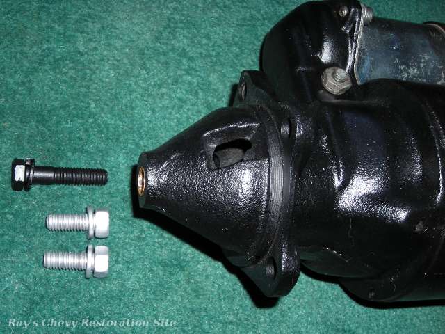
This style of drive end is used on early manual transmission applications where the starter bolts to the bellhousing. I think it may have also been used on some early automatic transmissions such as the cast iron Powerglide where it bolted to an adapter plate between the engine and transmission.
I believe this style was last used in Chevy cars in the early/mid 60's but continued to be used in pick-up trucks up until 1972.
It attaches with 3 bolts. Two ⅜"-16 x 1" long bolts go through the two un-threaded holes in the starter nose and screw into the bellhousing. One ⅜"-16 x 1-¾" long bolt goes through an un-threaded hole in the bellhousing and screws into the threaded hole in the starter nose.
Early 1955 - 56 versions of this style starter nose had all three bolts going through un-threaded holes in the starter nose and screwing into the bellhousing.
Cast Iron, 2 Bolts to Engine Block:
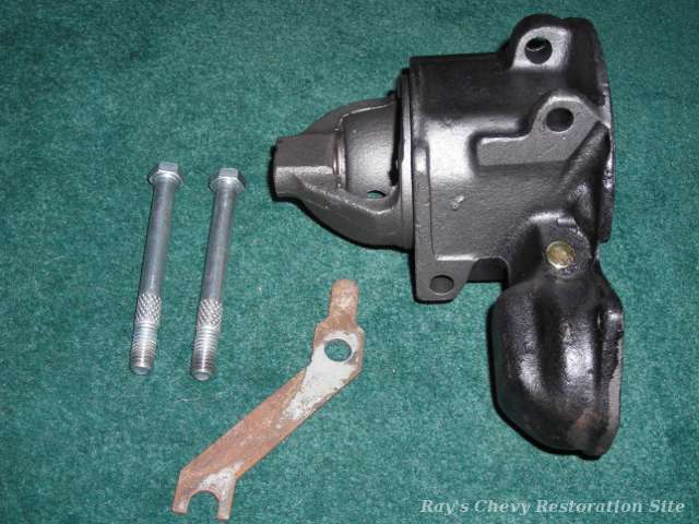
This style of drive end is used on later manual transmission applications where the starter bolts to the engine block. It is used with a 14" diameter, 168 tooth flywheel. It will also fit automatic transmission applications using a 14" diameter, 168 tooth flexplate.
It attaches with 2 equal length bolts in a staggered (one farther ahead than the other) pattern. Both bolts are ⅜"-16 x 3-⅝" long and feature special knurled shanks to ensure a snug fit in the holes.
Also shown in the photo is an example of the type of shim that is sometimes needed with this style of starter nose. See Starter Shimming section for details.
Note: This style of drive end can also be used with automatic transmissions in applications that use a 14" diameter, 168 tooth flexplate.
Cast Iron, 3 Bolts to Engine Block:
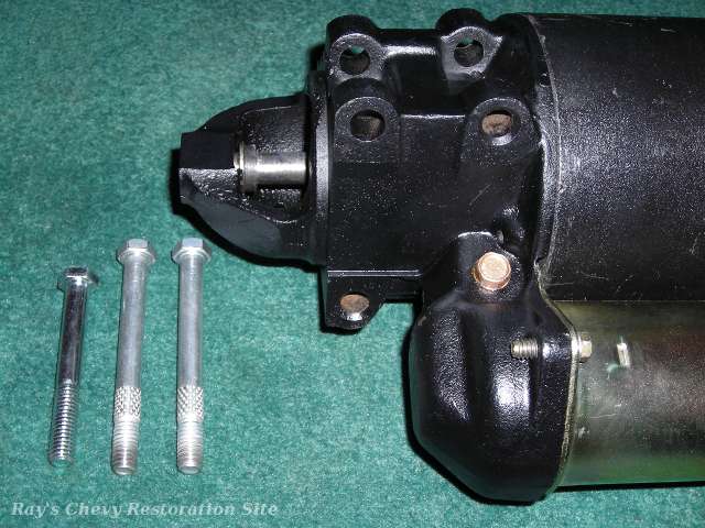
This style of drive end is used on many 348, 409, and early big block applications that don't use the bellhousing mounted starter. I believe it was also used on a few small block applications from the mid 60's and into the early 70's. These were used with both manual and automatic transmissions having a 14" diameter, 168 tooth flywheel or flexplate.
This drive end is very similar to the 2-bolt cast iron nose shown above except for the additional bolt hole. It uses two of the same size ⅜"-16 x 3-⅝" knurled shank bolts as the 2-bolt iron nose. The additional hole takes a ⅜"-16 x 3" bolt without the knurled shank.
Shimming might sometimes be needed with this nose. See Starter Shimming section for details.
Important: The 3rd hole on this style of drive end will NOT line up with the bolt pattern on engine blocks that are not specifically drilled for this pattern. See the Engine Block Bolt Hole Patterns section for details.
Aluminum, 2 Bolts to Engine Block, Straight Across:
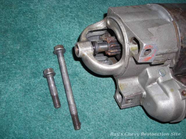
This style of drive end is used on most automatic transmission applications using a 12-¾" diameter, 153 tooth flexplate. It might also be used on manual transmission applications using a 12-¾" diameter, 153 tooth flywheel.
It attaches with two mounting bolts in a straight across pattern. The long bolt in closest to the engine is ⅜"-16 x 4-⅝". The short outboard bolt is ⅜"-16 x 1-⅞". Both bolts have knurled shanks to ensure a snug fit in the holes.
Not shown in this photo is the style of shim (straight style) that is sometimes needed with this nose. See Starter Shimming section for details.
Aluminum, 2 Bolts to Engine Block, Staggered Pattern:
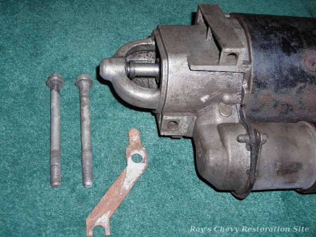
This style of drive end is used on most automatic transmission applications using a 14" diameter, 168 tooth flexplate.
It attaches with 2 equal length bolts in a staggered (one farther ahead than the other) pattern. Both bolts are ⅜"-16 x 4-⅝" long and feature special knurled shanks to ensure a snug fit in the holes.
Important: This style of drive end will NOT work with most manual transmission applications because it is too large to fit into the opening in the bellhousing. Instead, use the cast iron 2-bolt to block, staggered pattern drive end for manual transmissions w/168 tooth flywheels.
Also shown in the photo is an example of the type of shim that is sometimes needed with this style of starter nose. See Starter Shimming section for details.
Engine Block Bolt Hole Patterns
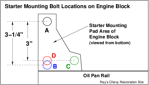
The starter mounting bolt hole pattern is not the same for all Chevrolet engine blocks.
- Aluminum drive ends with the 2-bolt straight-across pattern use holes A & B.
- Cast iron and aluminum drive ends with the 2-bolt staggered pattern use holes A & C
- Cast iron drive ends with the 3-bolt pattern use holes A, C, & D
Most 1962 & newer blocks are drilled with holes A, B, and C, allowing them to accept either the 2-bolt straight across starter drive for 153 tooth flywheels/flexplates or the 2-bolt staggered starter drive for 168 tooth flywheels/flexplates.
Many 400 cubic inch small blocks are only drilled with holes A and C for the 2-bolt staggered starter drive used with 168 tooth flywheels/flexplates.
Only certain blocks (mostly 348, 409, and early big blocks) are drilled with holes A, C, and D for use with the 3-bolt cast iron drive end. Blocks with this pattern will also accept the 2-bolt staggered drive ends.
Starter Bolts -- SAE vs. Metric
As mentioned in the various drive end descriptions, starters that bolt to the block require special bolts with a knurled shank to ensure a snug fit in the holes and prevent the starter from moving. The traditional size for these bolts is ⅜"-16 thread with a corresponding ⅜" diameter shank.
Many newer GM starters use bolts with a slightly larger 10mm shank that will be a sloppy fit if used with ⅜" bolts. This can be an issue with some remanufactured starters that have been fitted with an incorrect (newer style) nose cone with the larger 10mm holes. Or when installing a newer style PMGR (Permanent Magnet Gear Reduction) starter onto an older engine. I believe GM offers some special bolts just for this purpose. GM # 12338064 bolts have a 10mm shank combined with ⅜" threads and are 4.330" long. And GM # 14037733 have a 10mm shank with ⅜ threads and are 1.66" long.
Starter Braces
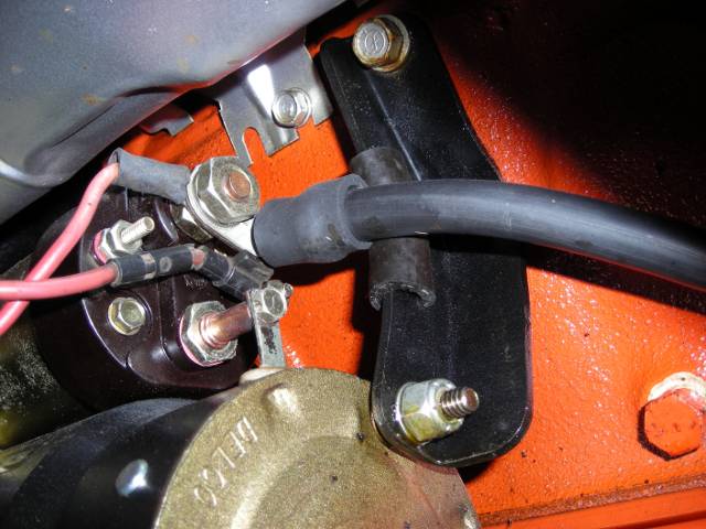
Many applications use a brace to support the forward end of the starter motor. These braces are commonly left off when starters are replaced, but should always be re-installed to prevent cracked nose pieces (especially with the aluminum ones).
The photo above shows a typical starter brace installation. Always tighten the starter mounting bolts before tightening the brace nut/bolt.
Starter Shimming
With the engine block mounted starters, it is sometimes necessary to add shims between the block and starter for proper pinion to ring gear spacing.
Methods for Checking Pinion to Ring Gear Spacing
A -- Measure Between the Teeth:
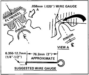
Clearance from the tip of a pinion tooth to the root of the ring gear should be in the 0.020" to 0.035" range. A feeler gauge can be formed from a section of 0.020" diameter wire as shown in the diagram to the right (from a GM service manual). Or, a standard paper clip (about 0.035" diameter) will work as well.
This method requires the pinion gear to be pulled out into the engaged position. That can be accomplished using any one of the following:
- Disconnect the battery and use a screwdriver or small pry bar to move the pinion gear.
- Or disconnect the battery cable from the large "B" stud on the starter solenoid and apply battery voltage to only the small "S" stud.
- Or temporarily remove the solenoid and pull the plunger to engage the pinion for measuring.
B -- Measure Between the Pinion Shaft & Ring Gear:
Clearance between the outer edge of the ring gear and the starter pinion shaft should be very close to 1/8". The shank of an 1/8" drill bit or an 1/8" hex key (Allen wrench) can be used as a feeler gauge.
This method avoids having to pull the pinion gear out into the engaged position to take the measurement.
C -- Paint the Teeth:
Brush some paint or gear marking compound (the type typically used for axle ring & pinion gears) onto the starter pinion gear. Install and crank the starter. Remove the starter and examine the gear tooth contact pattern left in the paint.
This method is good for applications where the design of the transmission or bell housing makes measuring the clearance difficult or impossible.
Shim Selection
If the clearance is too small, it can be increased by adding a full length shim (such as the ones shown in some of the above photos) to move the starter farther away from the flywheel/flexplate. These shims are available in several different thicknesses.
If the clearance is too large, it can be decreased by adding a small shim between the starter and engine block only at the outboard bolt location.
Note: It is a good idea to rotate the engine (by hand) and take multiple clearance measurements at several points around the ring gear. Ideally, they should all be the same if the ring gear is round and true.
- Return to Ray's Chevy Restoration Site Home Page
- e-mail:ray_mcavoy@yahoo.com
- © 1998 - 2023 Raymond McAvoy. All Rights Reserved.