Loose throttle shafts due to worn baseplate shaft bores are a common problem on high mileage QuadraJet carburetors. This results in vacuum leaks and throttle plate mis-alignment.
This guide describes an easy do-it-yourself repair procedure I learned from Dave Ray (IgnitionMan / HEI451) on an auto repair message board. The repair uses homemade Teflon (PTFE) "bushings". Unlike metal bushings, this repair does not require any special tools or involve any drilling, reaming, or other modifications to the carburetor baseplate. Instead, it simply makes use of the "stepped bore" that is already present in the baseplate from the factory.
Note: This procedure is not just limited to QuadraJet carburetors. It can be used on most any carburetor that has "stepped bore" holes for the throttle shaft(s). For example, I have also used it to repair a Nikki carburetor on an Onan P220G twin cylinder engine.
Photo #1
This shows the throttle not completely closing against the idle speed adjustment screw as a result of throttle plate mis-alignment allowing the plates to hit the sides of the throttle bores.
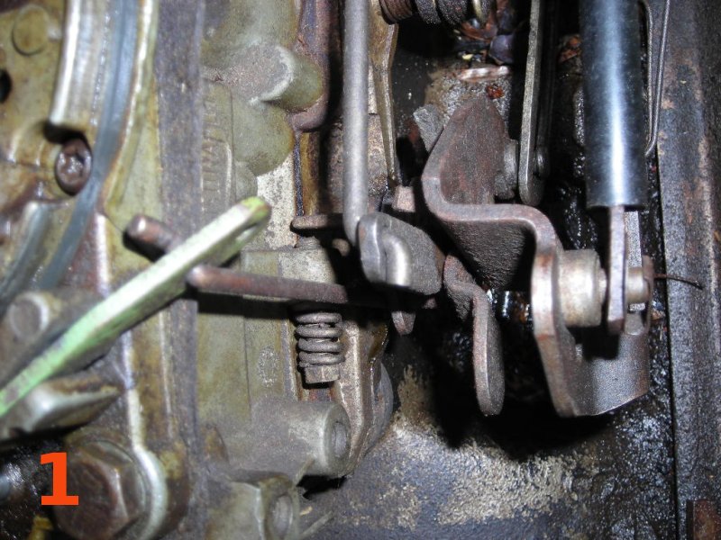
Important: Throttle shaft mis-alignment is not the only thing that will prevent the throttle from returning to the normal idle position. Be sure to first check the linkage/cable for binding and make sure the choke and fast idle mechanism are functioning properly.
Photo #2
Here is a reference photo showing the fast idle cam mechanism (stamped with a "Y" on this particular carb). Note that the choke (converted to manual on this carb) is open and the fast idle cam is down in the "regular idle" position. Please excuse the messy engine ... these photos are of my old snowplow truck.
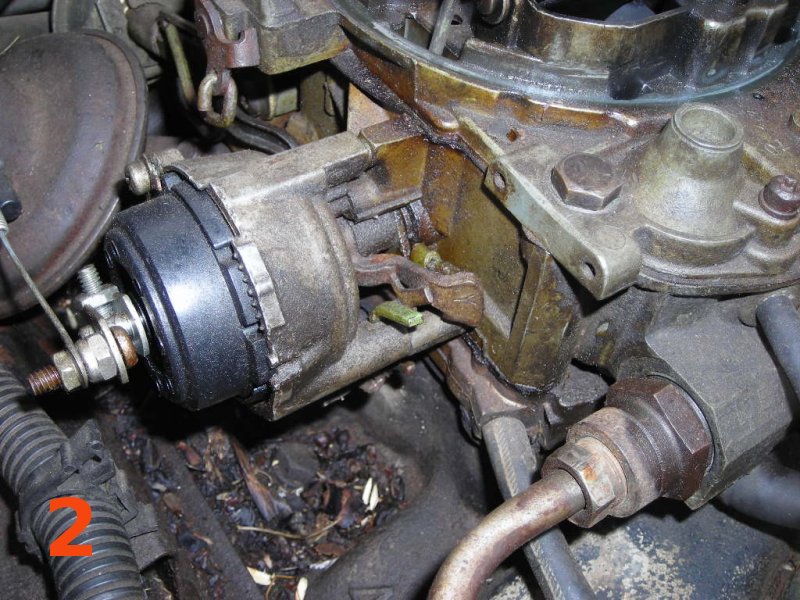
Photo #3
This is the baseplate removed from the carb along with the parts (Teflon sheet and screws) necessary for the repair.
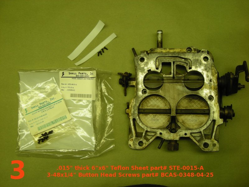
The Polytetrafluoroethylene (PTFE) (DuPont trade name Teflon) sheet needed for this repair is 0.015" thick. This thickness does not vary based on the amount of wear present. Instead, it is determined by the clearance between the throttle shaft and the (usually un-worn) larger diameter portion of the factory stepped bore in the baseplate. As a result, this repair method may not be suitable for carburetors with severe wear that has also damaged the larger portion of the stepped bore. I've heard that these Teflon sheets are available at many hobby & craft stores but I couldn't find any locally.
The factory screws used to secure the throttle plates to the shaft are 3-48 machine screws about ¼" long. And a throttle shaft with damaged / stripped threads could be re-tapped to use 4-40 screws. I did find some 3-48 and 4-40 machine screws at my local hardware stores but the shortest length they carry is ½" (these would work if cut shorter).
So I did some checking online and ended up purchasing the parts from SmallParts.com. The 6" x 6" x 0.015" thick Teflon sheet is part# STE-0015-A and is plenty to repair several carburetors. The 3-48 x ¼" Button head machine screws are part# BCAS-0348-04-25 for a pack of 25 that's enough to do 6 primary shafts (or 3 complete carbs).
UPDATE: Since this guide was written, www.smallparts.com changed over to selling through Amazon (instead of their own website). Unfortunately, the Amazon link I had for them no longer works. However, the Teflon sheets and 3-48 machine screws are available through McMaster Carr:
Screws are also available from other sources such as QuadrajetParts.com and BoltDepot.com
Photo #4
Here is a quick "before" measurement of the throttle shaft looseness. With about .020" of play, the shaft felt noticibly loose when wiggling the throttle lever.
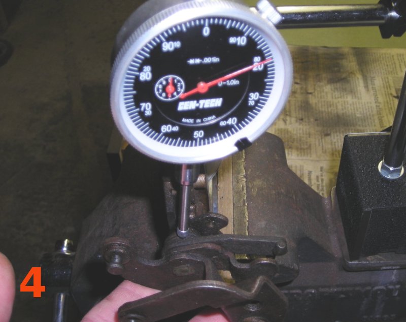
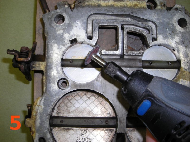
Photo #5
Use a Dremel (or similar rotary tool) to carefully grind off the staked ends of the throttle plate screws. Attempting to remove the screws without doing this will usually result in the heads twisting off. Or the threads in the shaft being damaged by the staked ends of the screws being backed through them.
With the staked ends ground off, simply unscrew the screws to remove the throttle plates. Take note of their position for re-assembly time. It will also be necessary to remove the linkage connecting the primary and secondary throttle shafts as well as the fast idle tang on the end of the primary shaft. Check with a repair manual if you need more info on removing these pieces. With all that out of the way, the primary throttle shaft (with lever attached) will slide right out of the baseplate.
Photo #6
This is the "stepped bore" that's present on all QuadraJet baseplates from the factory. It is what allows the Teflon "bushings" to be installed without any drilling. The shaft only rides on the inner (smaller) part, leaving the outer (larger) part unworn in all but the most extreme cases.
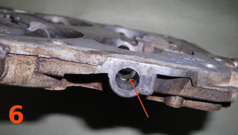
Photo #7
This shows the shaft laying on the baseplate. The orange arrows are pointing out the worn areas of the shaft that were riding on the smaller stepped down parts of the bore. The white arrows are pointing out the unworn areas of the shaft that were in the larger stepped up parts of the bore (this is where the homemade "bushings" will go).
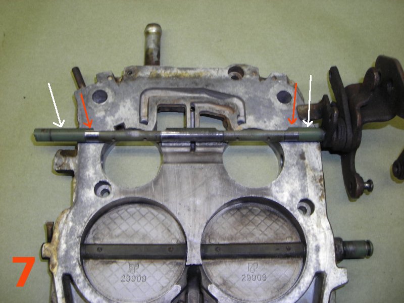
Photo #8
Here is one of the homemade "bushings" partially installed in the baseplate. Another "bushing" is temporarily placed in position on the throttle shaft for reference. These "bushings" are made by simply cutting the .015" thick Teflon sheet into approx ⅜" by 1" rectangles and rolling them into a loop.
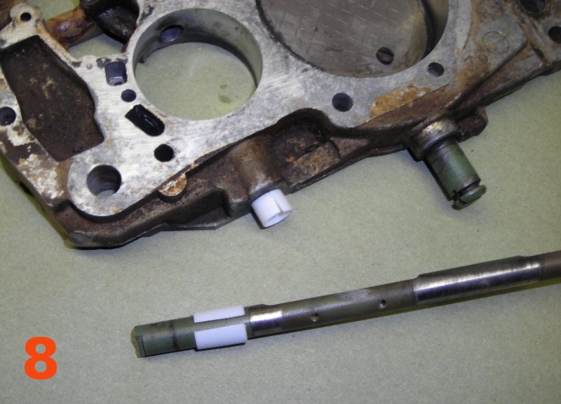
Photo #9
This shows the driver side bushing being installed. With the bushing partially inserted into the baseplate, carefully slide in the throttle shaft.
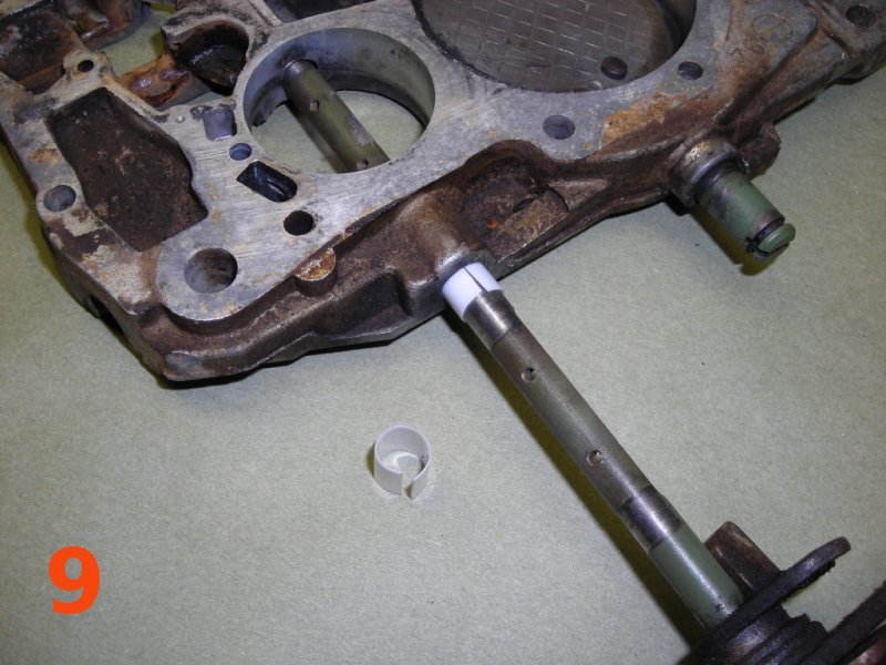
Photo #10
This shows the passenger side bushing being installed. Carefully slide it in between the shaft and baseplate bore.
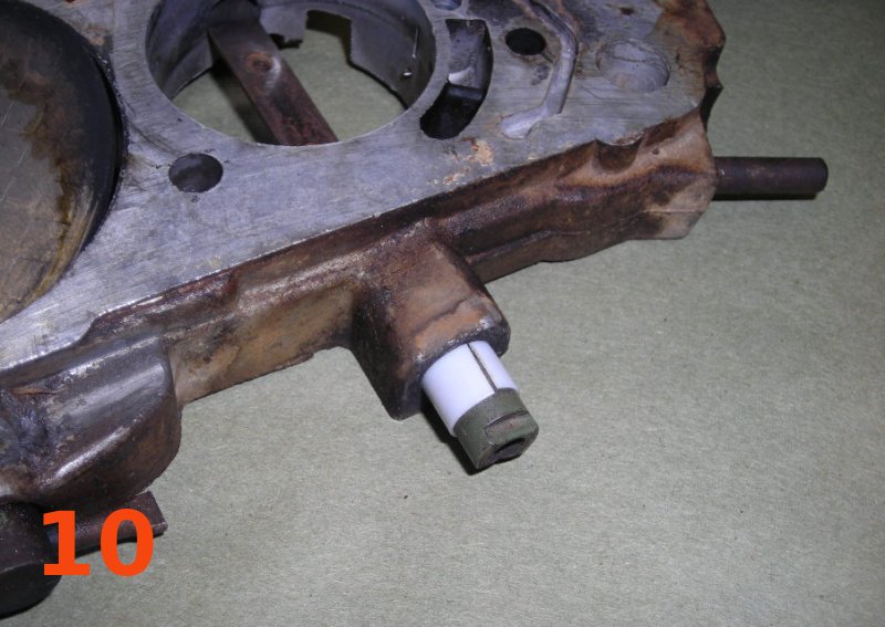
Photo #11
Here is an close up view showing the bushing fully installed flush with the edge of the baseplate. The .015" thick Teflon is a perfect fit in the factory stepped baseplate bore. The external linkage (once installed) will keep the Teflon from working it's way back out of the bore. And the bore's inner step forms a stop that keeps the Teflon from moving inward.
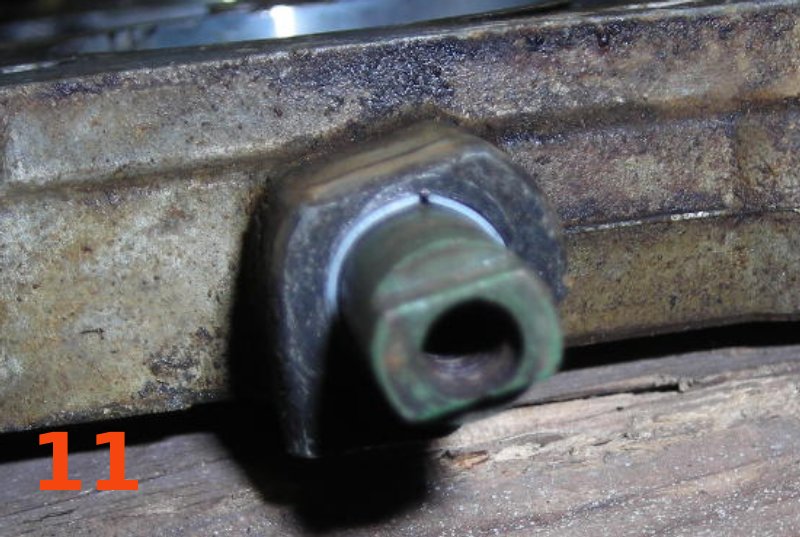
Photo #12
Re-install the throttle plates with the new 3-48 x ¼" screws. Make sure the throttle plates are fitting properly in the bores before fully tightening the screws. Use Loctite on the threads and deform the protruding ends of the screws by "staking" them or squeezing them with vice grips. You don't want these screws backing out and going down inside your engine.
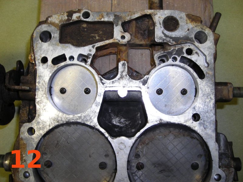
Photo #13
This shows an "after" measurement taken in a similar manner as photo #4. The play is down to .004" and not even noticible when wiggling the throttle shaft lever.
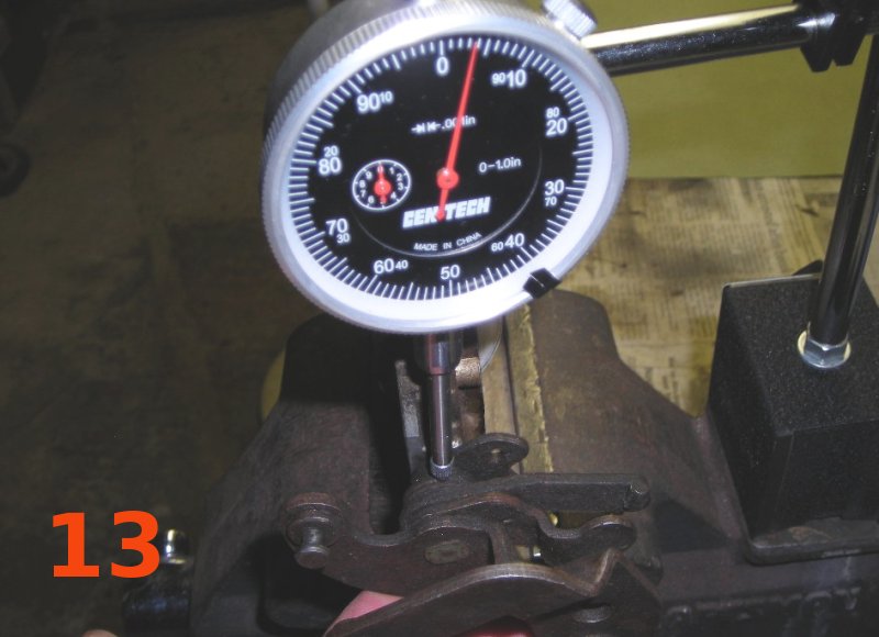
With the carb re-installed, the throttle now returns to the idle position normally. As with most, this particular carb only needed bushings on the primary shaft, but the secondary shaft can be done using the same procedure if necessary.
How Long Do They Last?
UPDATE: Since publishing this guide, I have received a few emails asking about how long these Teflon "bushings" last and/or how they hold up to engine heat.
I have repaired 3 Quadrajets using this method, with the first one being done in 2006 (17 years ago for this 2023 update). None of them are on "daily driver" vehicles that see lots of use, but so far they are all still working great with no noticeable wear or other issues with the bushings.
- Return to Ray's Chevy Restoration Site Home Page
- e-mail:ray_mcavoy@yahoo.com
- © 1998 - 2023 Raymond McAvoy. All Rights Reserved.